
 Altivar 61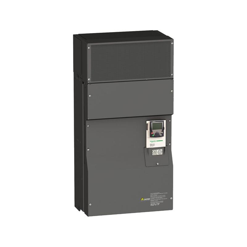
Schneider Electric catalog image for this SKU; may represent the product family.
VARIABLE SPEED DRIVE
SPEED DRIVE 125 HP 460 V ATV61
SKU ATV61HD90N4Schneider Electric ATV61HD90N4 is a variable speed drive in the Altivar 61 range. Key specifications include motor power: 90 kW, 3 phases at 380...480 V; net weight: 84 kg; product range: Altivar 61.
90 kW, 3 phases at 380...480 VMotor power
84 kgNet weight
Altivar 61Product range
PRODUCT DATA
Technical specifications
Source: Schneider Electric product catalog.
Verified September 18, 2026.
| Product reference | ATV61HD90N4 |
|---|---|
| Range of product | Altivar 61 |
| Product or component type | Variable speed drive |
| Product specific application | Pumping and ventilation machine |
| Component name | ATV61 |
| Motor power kW | 90 kW, 3 phases at 380...480 V |
| Motor power hp | 125 hp, 3 phases at 380...480 V |
| power supply voltage | 380...480 V - 15...10 % |
| supply number of phases | 3 phases |
| Line current | 143 A for 480 V 3 phases 90 kW / 125 hp 166 A for 380 V 3 phases 90 kW / 125 hp |
| EMC filter | Level 3 EMC filter |
| Assembly style | With heat sink |
| Apparent power | 109.3 kVA at 380 V 3 phases 90 kW / 125 hp |
| maximum prospective line Isc | 35 kA for 3 phases |
| Maximum transient current | 214.8 A for 60 s, 3 phases |
| Nominal switching frequency | 4 kHz |
| Switching frequency | 2...8 kHz adjustable 4...8 kHz with derating factor |
| asynchronous motor control | Voltage/frequency ratio, 5 points Voltage/frequency ratio, 2 points Flux vector control without sensor, standard Voltage/frequency ratio - Energy Saving, quadratic U/f |
| Synchronous motor control profile | Vector control without sensor, standard |
| Communication port protocol | Modbus CANopen |
| Type of polarization | No impedance for Modbus |
| Option card | Communication card for APOGEE FLN Communication card for BACnet Communication card for CC-Link Controller inside programmable card for Modbus Plus Communication card for DeviceNet Communication card for EtherNet/IP Communication card for Fipio I/O extension card for Profibus DP Communication card for Interbus-S Communication card for LonWorks Communication card for METASYS N2 Communication card for Modbus Plus Communication card for Modbus TCP Communication card for Modbus/Uni-Telway Multi-pump card for Fipio Communication card for Profibus DP Communication card for Profibus DP V1 |
| Product destination | Asynchronous motors Synchronous motors |
| power supply voltage limits | 323…528 V |
| power supply frequency | 50...60 Hz - 5...5 % |
| power supply frequency limits | 47.5...63 Hz |
| Continuous output current | 179 A at 4 kHz, 380 V - 3 phases 179 A at 4 kHz, 460 V - 3 phases |
| Output frequency | 0.1…500 Hz |
| Speed range | 1…100 in open-loop mode, without speed feedback |
| Speed accuracy | +/- 10 % of nominal slip 0.2 Tn to Tn without speed feedback |
| Torque accuracy | +/- 15 % in open-loop mode, without speed feedback |
| Transient overtorque | 130 % of nominal motor torque +/- 10 % for 60 s |
| Braking torque | <= 125 % with braking resistor 30 % without braking resistor |
| Regulation loop | Frequency PI regulator |
| Motor slip compensation | Automatic whatever the load Can be suppressed Not available in voltage/frequency ratio (2 or 5 points) Adjustable |
| diagnostic | 1 LED (red) for drive voltage |
| Output voltage | <= power supply voltage |
| electrical isolation | Between power and control terminals |
| type of cable for mounting in an enclosure | With an IP21 or an IP31 kit: 3 wire(s)IEC cable at 40 °C, copper 70 °C / PVC With UL Type 1 kit: 3 wire(s)UL 508 cable at 40 °C, copper 75 °C / PVC Without mounting kit: 1 wire(s)IEC cable at 45 °C, copper 70 °C / PVC Without mounting kit: 1 wire(s)IEC cable at 45 °C, copper 90 °C / XLPE/EPR |
| Electrical connection | Terminal 2.5 mm² / 14 AWG (AI1-/AI1+, AI2, AO1, R1A, R1B, R1C, R2A, R2B, LI1...LI6, PWR) Terminal 2 x 100 mm² / 2 x 250 kcmil (L1/R, L2/S, L3/T, U/T1, V/T2, W/T3) Terminal 60 mm² / 250 kcmil (PA, PB) Terminal 2 x 100 mm² / 2 x 250 kcmil (PC/-, PO, PA/+) |
| Tightening torque | 0.6 N.m (AI1-/AI1+, AI2, AO1, R1A, R1B, R1C, R2A, R2B, LI1...LI6, PWR) 24 N.m, 212 lb.in (L1/R, L2/S, L3/T, U/T1, V/T2, W/T3) 41 N.m, 360 lb.in (PC/-, PO, PA/+) 12 N.m, 106 lb.in (PA, PB) |
| Supply | Internal supply for reference potentiometer (1 to 10 kOhm): 10.5 V DC, +/- 5 %, <10 mA with overload and short-circuit protection Internal supply: 24 V DC (21…27 V), <200 mA with overload and short-circuit protection External supply: 24 V DC (19…30 V) |
| Analogue input number | 2 |
| Analogue input type | AI1-/Al1+ bipolar differential voltage: +/- 10 V DC 24 V max, resolution 11 bits + sign AI2 software-configurable current: 0...20 mA, impedance: 242 Ohm, resolution 11 bits AI2 software-configurable voltage: 0...10 V DC 24 V max, impedance: 30000 Ohm, resolution 11 bits |
| sampling time | 2 ms +/- 0.5 ms (AI1-/Al1+) - analog input 2 ms +/- 0.5 ms (Al2) - analog input 2 ms +/- 0.5 ms (AO1) - analog output 2 ms +/- 0.5 ms (LI1...LI5) - discrete input 2 ms +/- 0.5 ms (LI6)if configured as logic input - discrete input |
| absolute accuracy precision | +/- 0.6 % (AI1-/Al1+) for a temperature variation 60 °C +/- 0.6 % (AI2) for a temperature variation 60 °C +/- 1 % (AO1) for a temperature variation 60 °C |
| Linearity error | +/- 0.15 % of maximum value (AI1-/Al1+) +/- 0.15 % of maximum value (AI2) +/- 0.2 % (AO1) |
| Analogue output number | 1 |
| Analogue output type | AO1 software-configurable current, analogue output range 0...20 mA, impedance: 500 Ohm, resolution 10 bits AO1 software-configurable voltage, analogue output range 0...10 V DC, impedance: 470 Ohm, resolution 10 bits AO1 software-configurable logic output 10 V, 20 mA |
| Discrete output number | 2 |
| Discrete output type | Configurable relay logic: (R1A, R1B, R1C) NO/NC - 100000 cycles Configurable relay logic: (R2A, R2B) NO - 100000 cycles |
| maximum response time | <= 100 ms in STO (Safe Torque Off) R1A, R1B, R1C <= 7 ms, tolerance +/- 0.5 ms R2A, R2B <= 7 ms, tolerance +/- 0.5 ms |
| Minimum switching current | 3 mA at 24 V DC for configurable relay logic |
| Maximum switching current | R1, R2: 2 A at 250 V AC inductive load, cos phi = 0.4 and L/R = 7 ms R1, R2: 2 A at 30 V DC inductive load, cos phi = 0.4 and L/R = 7 ms R1, R2: 5 A at 250 V AC resistive load, cos phi = 1 and L/R = 0 ms R1, R2: 5 A at 30 V DC resistive load, cos phi = 1 and L/R = 0 ms |
| Discrete input number | 7 |
| Discrete input type | Programmable (LI1...LI5)24 V DC (<= 30 V), with level 1 PLC - 3500 Ohm Switch-configurable (LI6)24 V DC (<= 30 V), with level 1 PLC - 3500 Ohm Switch-configurable PTC probe (LI6)0…6 probes - 1500 Ohm Safety input (PWR)24 V DC (<= 30 V) - 1500 Ohm |
| Discrete input logic | Negative logic (sink) (LI1...LI5), > 16 V (state 0), < 10 V (state 1) Positive logic (source) (LI1...LI5), < 5 V (state 0), > 11 V (state 1) Negative logic (sink) (LI6)if configured as logic input, > 16 V (state 0), < 10 V (state 1) Positive logic (source) (LI6)if configured as logic input, < 5 V (state 0), > 11 V (state 1) |
| Acceleration and deceleration ramps | Linear adjustable separately from 0.01 to 9000 s S, U or customized Automatic adaptation of ramp if braking capacity exceeded, by using resistor |
| Braking to standstill | By DC injection |
| Protection type | Against exceeding limit speed: drive Against input phase loss: drive Break on the control circuit: drive Input phase breaks: drive Line supply overvoltage: drive Line supply undervoltage: drive Overcurrent between output phases and earth: drive Overheating protection: drive Overvoltages on the DC bus: drive Power removal: drive Short-circuit between motor phases: drive Thermal protection: drive Motor phase break: motor Power removal: motor Thermal protection: motor |
| Insulation resistance | > 1 mOhm 500 V DC for 1 minute to earth |
| Frequency resolution | Analog input: 0.024/50 Hz Display unit: 0.1 Hz |
| Connector type | 1 RJ45 (on front face) for Modbus 1 RJ45 (on terminal) for Modbus Male SUB-D 9 on RJ45 for CANopen |
| Physical interface | 2-wire RS 485 for Modbus |
| Transmission frame | RTU for Modbus |
| Transmission rate | 4800 bps, 9600 bps, 19200 bps, 38.4 Kbps for Modbus on terminal 9600 bps, 19200 bps for Modbus on front face 20 kbps, 50 kbps, 125 kbps, 250 kbps, 500 kbps, 1 Mbps for CANopen |
| Data format | 8 bits, 1 stop, even parity for Modbus on front face 8 bits, odd even or no configurable parity for Modbus on terminal |
| Number of addresses | 1…127 for CANopen 1…247 for Modbus |
| Method of access | Slave CANopen |
| Marking | CE |
| Operating position | Vertical +/- 10 degree |
| Net weight | 84 kg |
| Width | 320 mm |
| Height | 920 mm |
| Depth | 377 mm |
| Noise level | 60.5 dB conforming to 86/188/EEC |
| Dielectric strength | 3535 V DC between earth and power terminals 5092 V DC between control and power terminals |
| Electromagnetic compatibility | Conducted radio-frequency immunity test level 3 conforming to IEC 61000-4-6 Electrical fast transient/burst immunity test level 4 conforming to IEC 61000-4-4 Electrostatic discharge immunity test level 3 conforming to IEC 61000-4-2 Radiated radio-frequency electromagnetic field immunity test level 3 conforming to IEC 61000-4-3 Voltage dips and interruptions immunity test conforming to IEC 61000-4-11 |
| Standards | IEC 61800-3 environments 2 category C3 EN 55011 class A group 2 UL Type 1 IEC 60721-3-3 class 3C2 IEC 61800-5-1 IEC 61800-3 environments 1 category C3 IEC 61800-3 |
| Product certifications | C-Tick DNV GOST CSA UL NOM 117 |
| Pollution degree | 3 conforming to IEC 61800-5-1 3 conforming to UL 840 |
| degree of proctection | IP41 on upper part conforming to IEC 60529 IP41 on upper part conforming to IEC 61800-5-1 IP54 on lower part conforming to IEC 60529 IP54 on lower part conforming to IEC 61800-5-1 IP00 on lower part conforming to IEC 60529 IP00 conforming to IEC 61800-5-1 IP30 on side parts conforming to IEC 60529 IP30 on side parts conforming to IEC 61800-5-1 IP30 on the front panel conforming to IEC 60529 IP30 on the front panel conforming to IEC 61800-5-1 |
| Vibration resistance | 0.6 gn (f= 10…200 Hz) conforming to IEC 60068-2-6 1.5 mm peak to peak (f= 3…10 Hz) conforming to IEC 60068-2-6 |
| Shock resistance | 7 gn for 11 ms conforming to IEC 60068-2-27 |
| Relative humidity | 5…95 % without condensation conforming to IEC 60068-2-3 5…95 % without dripping water conforming to IEC 60068-2-3 |
| Ambient air temperature for operation | -10…45 °C (without derating) 45…60 °C (with derating factor) |
| Ambient air temperature for storage | -25…70 °C |
| Operating altitude | <= 1000 m without derating 1000...3000 m with current derating 1 % per 100 m |
For complete electrical ratings, applicable standards, connection requirements and installation instructions, consult the official Schneider Electric reference ↗.