
 TeSys Ultra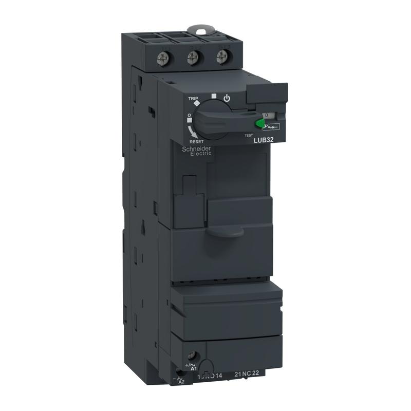
Schneider Electric catalog image for this SKU; may represent the product family.
NON REVERSING POWER BASE
Power base, TeSys U, 3P, 32A/690V
SKU LUB32Schneider Electric LUB32 is a non reversing power base in the TeSys Ultra range. Key specifications include auxiliary contacts: 1 NO + 1 NC; control voltage: 24 V AC 50/60 Hz; poles: 3P.
1 NO + 1 NCAuxiliary contacts
24 V AC 50/60 HzControl voltage
3PPoles
PRODUCT DATA
Technical specifications
Source: Schneider Electric product catalog.
Verified September 17, 2026.
| Product reference | LUB32 |
|---|---|
| Range | TeSys |
| Product name | TeSys Ultra |
| Device short name | LUB |
| Product or component type | Non reversing power base |
| Device application | Motor control Motor protection |
| Poles description | 3P |
| Suitability for isolation | Yes |
| [Ue] rated operational voltage | 690 V AC for power circuit |
| Network frequency | 40...60 Hz |
| [Ith] conventional free air thermal current | 32 A |
| [Ie] rated operational current | 32 A at <= 440 V 23 A at 500 V 21 A at 690 V |
| Utilisation category | AC-43 AC-44 AC-41 |
| [Ics] rated service breaking capacity | 50 kA at 230 V 50 kA at 440 V 10 kA at 500 V 4 kA at 690 V |
| Auxiliary contact composition | 1 NO + 1 NC |
| Auxiliary contacts type | type linked contacts (1 NO + 1 NC) conforming to IEC 60947-4-1 type mirror contact (1 NC) conforming to IEC 60947-1 |
| [Uc] control circuit voltage | 24 V AC 50/60 Hz 24 V DC 48...72 V AC 50/60 Hz 48...72 V DC 110...240 V AC 50/60 Hz 110...220 V DC |
| Typical current consumption | 200 mA at 24 V DC I maximum while closing with LUCM 220 mA at 24 V AC I maximum while closing with LUCA, LUCB, LUCC, LUCD 220 mA at 24 V DC I maximum while closing with LUCA, LUCB, LUCC, LUCD 25 mA at 110...220 V DC I rms sealed with LUCA, LUCB, LUCC, LUCD 25 mA at 110...240 V AC I rms sealed with LUCA, LUCB, LUCC, LUCD 280 mA at 110...220 V DC I maximum while closing with LUCA, LUCB, LUCC, LUCD 280 mA at 110...240 V AC I maximum while closing with LUCA, LUCB, LUCC, LUCD 280 mA at 48...72 V AC I maximum while closing with LUCA, LUCB, LUCC, LUCD 280 mA at 48...72 V DC I maximum while closing with LUCA, LUCB, LUCC, LUCD 45 mA at 48...72 V AC I rms sealed with LUCA, LUCB, LUCC, LUCD 45 mA at 48...72 V DC I rms sealed with LUCA, LUCB, LUCC, LUCD 75 mA at 24 V DC I rms sealed with LUCM 80 mA at 24 V DC I rms sealed with LUCA, LUCB, LUCC, LUCD 90 mA at 24 V AC I rms sealed with LUCA, LUCB, LUCC, LUCD |
| Heat dissipation | 3 W for control circuit with LUCA, LUCB, LUCC, LUCD 1.8 W for control circuit with LUCM |
| Safety reliability level | B10d = 1369863 cycles contactor with nominal load conforming to EN/ISO 13849-1 B10d = 20000000 cycles contactor with mechanical load conforming to EN/ISO 13849-1 |
| Operating time | 35 ms opening with LUCA, LUCB, LUCC, LUCD, LUCM for control circuit 50 ms at >= 72 V closing with LUCA, LUCB, LUCC, LUCD for control circuit 60 ms at 48 V closing with LUCA, LUCB, LUCC, LUCD for control circuit 70 ms at 24 V closing with LUCA, LUCB, LUCC, LUCD for control circuit 65 ms closing with LUCM for control circuit |
| Mechanical durability | 15 Mcycles |
| maximum operating rate | 3600 cyc/h |
| Product certifications | CE UL CSA CCC EAC ASEFA ATEX Marine |
| Standards | EN 60947-6-2 IEC 60947-6-2 UL 60947-4-1, with phase barrier CSA C22.2 No 60947-4-1, with phase barrier |
| [Ui] rated insulation voltage | 690 V conforming to IEC 60947-6-2 (pollution degree 3) 600 V conforming to UL 60947-4-1 600 V conforming to CSA C22.2 No 60947-4-1 |
| [Uimp] rated impulse withstand voltage | 6 kV conforming to IEC 60947-6-2 |
| Safe separation of circuit | 400 V SELV between the control and auxiliary circuits conforming to IEC 60947-1 appendix N 400 V SELV between the control or auxiliary circuit and the main circuit conforming to IEC 60947-1 appendix N |
| Fixing mode | Clipped (DIN rail) Screw-fixed (plate) |
| Connections - terminals | Control circuit: screw clamp terminals 1 cable(s) 0.34…1.5 mm² flexible with cable end Control circuit: screw clamp terminals 1 cable(s) 0.75…1.5 mm² flexible without cable end Control circuit: screw clamp terminals 1 cable(s) 0.75…1.5 mm² rigid Control circuit: screw clamp terminals 2 cable(s) 0.34…1.5 mm² flexible with cable end Control circuit: screw clamp terminals 2 cable(s) 0.75…1.5 mm² flexible without cable end Control circuit: screw clamp terminals 2 cable(s) 0.75…1.5 mm² rigid Power circuit: screw clamp terminals 1 cable(s) 1…10 mm² rigid Power circuit: screw clamp terminals 1 cable(s) 1…6 mm² flexible with cable end Power circuit: screw clamp terminals 1 cable(s) 2.5…10 mm² flexible without cable end Power circuit: screw clamp terminals 2 cable(s) 1…6 mm² flexible with cable end Power circuit: screw clamp terminals 2 cable(s) 1…6 mm² rigid Power circuit: screw clamp terminals 2 cable(s) 1.5…6 mm² flexible without cable end |
| Tightening torque | Control circuit: 0.8…1.2 N.m flat screwdriver 5 mm Control circuit: 0.8…1.2 N.m Philips no 1 screwdriver 5 mm Power circuit: 1.9…2.5 N.m flat screwdriver 6 mm Power circuit: 1.9…2.5 N.m Philips No 2 screwdriver 6 mm Power circuit: 1.9…2.5 N.m pozidriv No 2 screwdriver 6 mm |
| Width | 45 mm |
| Height | 154 mm |
| Depth | 126 mm |
| Net weight | 0.9 kg |
| Compatibility code | LUB |
| IP degree of protection | IP20 conforming to IEC 60947-1 (front panel and wired terminals) IP20 conforming to IEC 60947-1 (other faces) IP40 conforming to IEC 60947-1 (front panel outside connection zone) |
| Protective treatment | TH conforming to IEC 60068 |
| Ambient air temperature for operation | -25…60 °C with LUCM -25…70 °C with LUCA, LUCB, LUCC, LUCD |
| Ambient air temperature for storage | -40…85 °C |
| Fire resistance | 960 °C parts supporting live components conforming to IEC 60695-2-12 650 °C conforming to IEC 60695-2-12 |
| Operating altitude | 2000 m |
| Shock resistance | 10 gn power poles open conforming to IEC 60068-2-27 15 gn power poles closed conforming to IEC 60068-2-27 |
| Vibration resistance | 2 gn (f= 5…300 Hz) power poles open conforming to IEC 60068-2-27 4 gn (f= 5…300 Hz) power poles closed conforming to IEC 60068-2-27 |
| Resistance to electrostatic discharge | 8 kV level 3 in open air conforming to IEC 61000-4-2 8 kV level 4 on contact conforming to IEC 61000-4-2 |
| Non-dissipating shock wave | 1 kV serial mode 24...240 V AC conforming to IEC 60947-6-2 1 kV serial mode 48...220 V DC conforming to IEC 60947-6-2 2 kV common mode 24...240 V AC conforming to IEC 60947-6-2 2 kV common mode 48...220 V DC conforming to IEC 60947-6-2 |
| Resistance to fast transients | 2 kV class 3 serial link conforming to IEC 61000-4-4 4 kV class 4 all circuits except for serial link conforming to IEC 61000-4-4 |
| Resistance to radiated fields | 10 V/m 3 conforming to IEC 61000-4-3 |
| Immunity to radioelectric fields | 10 V conforming to IEC 61000-4-6 |
| Immunity to microbreaks | 3 ms for control circuit |
| Immunity to voltage dips | 70 % / 500 ms conforming to IEC 61000-4-11 |
For complete electrical ratings, applicable standards, connection requirements and installation instructions, consult the official Schneider Electric reference ↗.