
 MasterPacT MTZ2 Active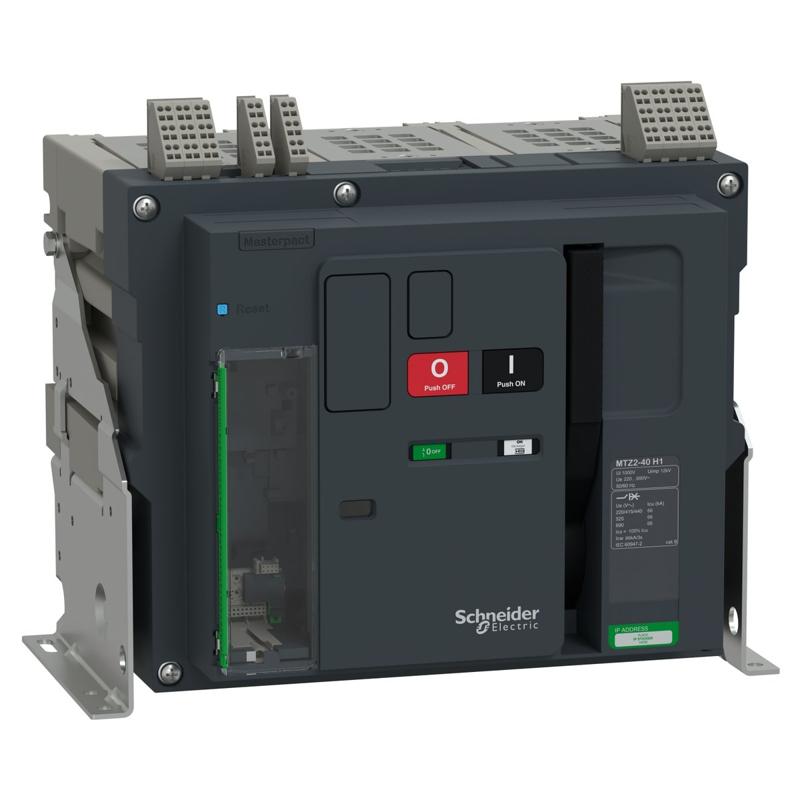
Schneider Electric catalog image for this SKU; may represent the product family.
CIRCUIT BREAKER
Circuit breaker, MasterPacT MTZ2 40H1 fixed, 3P, 4000A, 66kA/440VAC, MicroLogic 2.0E Active, manually operated, horizontal connections
SKU MTZ240_H12E3PMFHHSchneider Electric MTZ240_H12E3PMFHH is a circuit breaker in the MasterPacT MTZ2 Active range. Key specifications include rated current: 4000 A at 40 °C; poles: 3P; trip unit: MicroLogic Active 2.0 E.
4000 A at 40 °CRated current
3PPoles
MicroLogic Active 2.0 ETrip unit
PRODUCT DATA
Technical specifications
Source: Schneider Electric product catalog.
Verified September 06, 2026.
| Product reference | MTZ240_H12E3PMFHH |
|---|---|
| Range | MasterPacT |
| Product name | MasterPacT MTZ2 Active |
| Product or component type | Circuit breaker |
| Device short name | MTZ2 40 H1 |
| Device application | Power distribution |
| Poles description | 3P |
| Protected poles description | 3P 3d |
| [In] rated current | 4000 A at 40 °C |
| Performance type | H1 66 kA 415 V AC |
| [Ue] rated operational voltage | 690 V AC 50/60 Hz |
| Suitability for isolation | Yes conforming to EN/IEC 60947-2 |
| Selectivity category | Category B |
| Control type | Manually operated ON/OFF push-button |
| Mounting mode | Fixed |
| Trip unit name | MicroLogic Active 2.0 E |
| Trip unit technology | Electronic |
| Trip unit protection functions | LI |
| Sensor rating | 2000 A 2500 A 3200 A 4000 A |
| [Icu] rated ultimate short-circuit breaking capacity | 66 kA at 220/415 V AC 50/60 Hz 66 kA at 440 V AC 50/60 Hz 66 kA at 525 V AC 50/60 Hz 66 kA at 690 V AC 50/60 Hz |
| [Ics] rated service short-circuit breaking capacity | 66 kA at 220/415 V AC 50/60 Hz 66 kA at 440 V AC 50/60 Hz 66 kA at 525 V AC 50/60 Hz 66 kA at 690 V AC 50/60 Hz |
| [Icw] rated short-time withstand current | 66 kA 0.5 s 66 kA 1 s 36 kA 3 s |
| [Icm] rated short-circuit making capacity | 145 kA at 220/415 V AC 50/60 Hz 145 kA at 440 V AC 50/60 Hz 145 kA at 525 V AC 50/60 Hz 145 kA at 690 V AC 50/60 Hz |
| [Ui] rated insulation voltage | 1000 V AC 50/60 Hz |
| [Uimp] rated impulse withstand voltage | 12 kV |
| Power dissipation in W | 650 W |
| Power dissipation per pole | 216.7 W |
| Maximum breaking time | 25 ms |
| Maximum closing response time | 70 ms |
| Mounting support | Base plate Rails |
| Upside connection | Horizontal Rear |
| Downside connection | Horizontal Rear |
| Mechanical durability | 20000 cycles with maintenance |
| Electrical durability | 5000 cycles 440 V AC 50/60 Hz conforming to EN/IEC 60947-2 2500 cycles 690 V AC 50/60 Hz conforming to EN/IEC 60947-2 |
| Protection type | Overload protection (long time) conforming to ANSI 49 Instantaneous short-circuit protection conforming to ANSI 50 |
| Trip unit rating | 250 A 400 A 630 A 800 A 1000 A 1250 A 1600 A 2000 A 2500 A 3200 A 4000 A 5000 A 6300 A |
| Long-time pick-up adjustment type Ir (thermal protection) | Adjustable |
| [Ir] long-time protection pick-up adjustment range | 0.4...1 x In adjustable in step of 1 A |
| Long-time protection delay adjustment type tr | Adjustable in step of 0.5 s |
| [tr] long-time protection delay adjustment range | 0.5…30 s at 6 x Ir |
| Thermal memory | Yes |
| Instantaneous protection pick-up adjustment type Ii | Adjustable |
| [Ii] instantaneous protection pick-up adjustment range | 1.5...10 x Ir adjustable in step of 0.1 x Ir |
| [li mode] instantaneous delay adjustment range | 20 ms in standard |
| Earth-leakage protection | Without |
| Zone selective interlocking ZSI | Without |
| Network and machine diagnosis type | System (HMI) health state overview: circuit breaker health state Contacts state: circuit breaker health state MicroLogic service life: circuit breaker health state Tripping cause indication: circuit breaker tripping cause Identification card: diagnostic data Configured alarms synthesis: diagnostic data Monitored function: diagnostic data Operation: diagnostic data MicroLogic test: test Protection test: test Selectivity test: test Trip context information: crisis management Operation: advanced diagnostic Breaker service life: circuit breaker health state |
| Type of measurement | Energy meter Ammeter |
| Energy management | Measurement ,active, reactive and apparent energy Measurement ,electrical network Measurement ,energy |
| Metering type | Current I1, I2, I3, Iavg RMS Voltage V12, V23, V31, VLLavg RMS Active power P, P1, P2, P3 total Active energy Ep IN/OUT/tot Power factor Demand current I1, I2, I3, In, Iavg Frequency Phase sequence Unbalance current |
| Measurement voltage | 208…828 V AC 50/60 Hz phase to phase |
| Frequency measurement range | 40…70 Hz |
| Measurement accuracy | Current I1, I2, I3, Iavg, Idemand for MTZ2: +/- 1.5 % 40...4000 x 1.2 A Voltage V12, V23, V31, VLLavg: +/- 0.5 % 208...690 x 1.2 V Voltage V1N, V2N, V3N, VLNavg: +/- 0.5 % 120...400 x 1.2 V Active power P, P1, P2, P3, Pdemand: +/- 2 % Active energy Ep IN/OUT/tot: +/- 2 % Power factor: +/- 2 % Frequency: +/- 0.005 Hz Unbalance current: +/- 0.5 % |
| Accuracy class | Class 0.5: unbalance voltage |
| Display type | LCD display - 320 x 240 pixels |
| Local signalling | 2 LEDs for trip causes 3 LEDs for status indication |
| Communication port protocol | NFC peer to peer 28800 bauds conforming to ISO 15963 USB peer to peer 115 kbauds |
| Data recording | Data logs Event logs Alarm logs Time stamping Maintenance logs Min/max of instantaneous values |
| End user smartphone application | EcoStruxure Power Commission EcoStruxure Power Device |
| Width (W) | 422 mm |
| Height (H) | 352 mm |
| Depth (D) | 300 mm |
| Net weight | 50 kg |
| Standards | EN/IEC 60947-1 EN/IEC 60947-2 |
| Product certifications | CE CCC EAC |
| IP degree of protection | IP3X conforming to EN/IEC 60529 |
| IK degree of protection | IK07 conforming to EN/IEC 62262 |
| Pollution degree | 3 conforming to EN/IEC 60664-1 |
| Ambient air temperature for operation | -25…70 °C |
| Temperature derating table | 40 °C ( 4000 A ) 45 °C ( 4000 A ) 50 °C ( 4000 A ) 55 °C ( 3900 A ) 60 °C ( 3800 A ) 65 °C ( 3700 A ) 70 °C ( 3600 A ) |
| Ambient air temperature for storage | -40…85 °C |
| Relative humidity | 0…95 % conforming to IEC 60068-2-30 |
| Operating altitude | 0...2000 m without derating 2000 m...5000 m with derating factor |
For complete electrical ratings, applicable standards, connection requirements and installation instructions, consult the official Schneider Electric reference ↗.