
 PowerLogic PFC Controller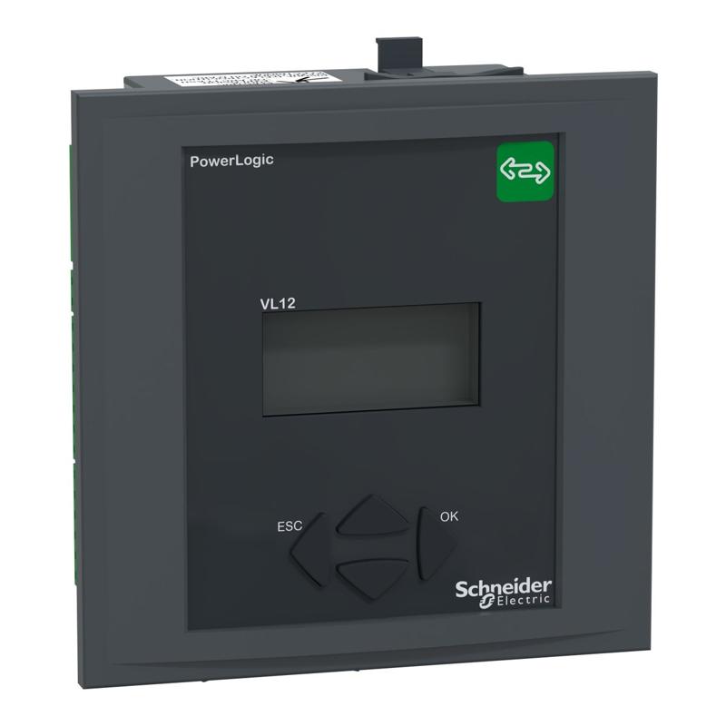
Schneider Electric catalog image for this SKU; may represent the product family.
POWER FACTOR CONTROLLER
Power Factor controller - VarPlus Logic - VPL 12
SKU VPL12NSchneider Electric VPL12N is a power factor controller in the PowerLogic PFC Controller range. Key specifications include mounting mode: Flush-mounted; mounting support: Panel - thickness: 1…3 mm; ip protection: Front face: IP41.
Flush-mountedMounting mode
Panel - thickness: 1…3 mmMounting support
Front face: IP41IP protection
PRODUCT DATA
Technical specifications
Source: Schneider Electric product catalog.
Verified September 17, 2026.
| Product reference | VPL12N |
|---|---|
| Range | PowerLogic |
| Product name | PowerLogic PFC Controller |
| Product or component type | Power factor controller |
| Device short name | VPL12 |
| Number of step output contacts | 12 |
| [Us] rated supply voltage | 90...550 V AC <= 999 kV AC with external VT |
| Measurement current | 0…5 A |
| Measurement voltage | 90…550 V AC 50/60 Hz |
| Operating mode | Manual or automatic |
| Number of quadrant operation for generator application | 4 |
| Device connection | Communication protocol: Modbus interface: RS485 |
| Input function | Switch: 1 x dry contact |
| Colour code | Front: dark grey RAL 7016 |
| Display type | Backlit LCD |
| Display size | 56 x 25 mm |
| Function available | Manual programming Automatic initialisation Automatic detection Advanced programming (expert) Any step sequence |
| Metering type | Power factor and displacement PF (signed, four quadrant) Total current harmonic distortion THD (I) Power factor average over lifetime Temperature maximum Phase current I1, I2, I3 RMS on load Active power P, P1, P2, P3 on load Reactive power Q, Q1, Q2, Q3 on load Apparent power S, S1, S2, S3 on load Voltage U21, U32, U13, V1, V2, V3 on load |
| Type of measurement | Capacitor current overload Irms/I1 Individual voltage harmonic Power factor Operating time Cos φ Ambient temperature inside the cubicle Tan φ |
| Information displayed | Number of switching cycles per step Individual step size in kVAr Remaining step capacity in % |
| Type of alarms | Step power loss (< 75 %) / Action: message and alarm contact + step blocked Step faulty / Action: message and alarm contact + step blocked High current (> 6 A CT) / Action: message and alarm contact Hunting (unstable regulation) / Action: message and alarm contact + step blocked Low current (< 15 mA CT) / Action: message and alarm contact Overcompensation / Action: message and alarm contact Capacitor current overload (Irms/I1) (> 130 % I1) / Action: message and alarm contact + step switched off Overtemperature (50 °C) / Action: message and alarm contact + step switched off Overtemperature (30 °C) / Action: fan switch Overvoltage (+/- 10 %) / Action: message and alarm contact + control stopped Total harmonic distortion (> 7 %) / Action: message and alarm contact + step switched off |
| Data recording | 5 alarms |
| Operational Hours alarm | 100000 h without maintenance |
| Operational counter alarm | 65000 cycles without maintenance |
| Input type | Phase to phase Phase to neutral Insensitive to CT polarity Insensitive to phase rotation polarity Current input CT...X/5 A and X/1 A |
| Output type | Control relay: 0.2 A 110 V DC Control relay: 1 A 48 V DC Control relay: 2 A 400 V AC 50/60 Hz Control relay: 1 A 24 V DC Control relay: 5 A 250 V AC 50/60 Hz Control relay: 5 A 120 V AC 50/60 Hz Fan: 5 A 250 V AC 50/60 Hz Fan: 1 A 48 V DC Alarm relay: 5 A 250 V AC 50/60 Hz Alarm relay: 1 A 48 V DC |
| Maximum at the common terminal | 10 A |
| Settings operating mode | Automatic Manual |
| Type of setting | Choice of stepping programs: auto Choice of stepping programs: LIFO Choice of stepping programs: linear Delay between 2 successive switch on the same step: 5...1200 s Step configuration programming: auto Step configuration programming: off Step configuration programming: fixed Target cos phi: 0.7 inductive...0.7 capacitive Target cos phi: dual cos φ |
| Measurement accuracy | Voltage +/- 1 % Current +/- 1 % Frequency +/- 1 % Energy (P,Q,S) +/- 2 % Cos φ +/- 2 % Total voltage harmonic distortion THD (U) +/- 2 % Individual voltage harmonic +/- 3 % Temperature +/- 3 °C |
| Time delay range | 1...6500 s (on reconnection) 1...6500 s (on response) |
| Provided equipment | User manual |
| Mounting mode | Flush-mounted |
| Mounting support | Panel - thickness: 1…3 mm |
| Mounting location | In cabinet |
| Cut-out dimensions | 138 x 138 mm |
| Height | 144 mm |
| Width | 144 mm |
| Depth | 58 mm |
| Net weight | 0.6 kg |
| Compatibility code | VPL 12 |
| Standards | IEC 61000-6-4 UL 61010-1 EN 61010-1 IEC 61000-6-2 IEC 61326-1 |
| Product certifications | EAC NRTL cNRTL CE |
| IP degree of protection | Front face: IP41 Rear face: IP20 |
| Operating altitude | <= 2000 m |
| Ambient air temperature for operation | -20…60 °C |
| Ambient air temperature for storage | -40…85 °C |
For complete electrical ratings, applicable standards, connection requirements and installation instructions, consult the official Schneider Electric reference ↗.