
 TeSys Deca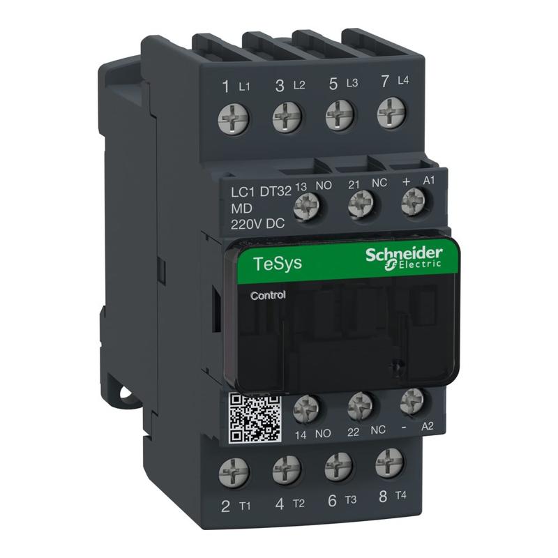
Schneider Electric catalog image for this SKU; may represent the product family.
CONTACTOR
Contactor, TeSys Deca, 4P(4 NO), AC-1, <=440V, 32A, 220VDC standard coil, screw clamp terminal
SKU LC1DT32MDSchneider Electric LC1DT32MD is a contactor in the TeSys Deca range. Key specifications include operational current: 32 A (at <60 °C) at <= 440 V AC AC-1 for power circuit; contact configuration: 4 NO; control voltage: 220 V DC.
32 A (at <60 °C) at <= 440 V AC AC-1 for power circuitOperational current
4 NOContact configuration
220 V DCControl voltage
PRODUCT DATA
Technical specifications
Source: Schneider Electric product catalog.
Verified September 18, 2026.
| Product reference | LC1DT32MD |
|---|---|
| Range | TeSys TeSys Deca |
| Range of product | TeSys Deca |
| Product or component type | Contactor |
| Device short name | LC1D |
| Contactor application | Resistive load |
| Utilisation category | AC-1 |
| Poles description | 4P |
| [Ue] rated operational voltage | Power circuit: <= 690 V AC 25...400 Hz Power circuit: <= 300 V DC |
| [Ie] rated operational current | 32 A (at <60 °C) at <= 440 V AC AC-1 for power circuit |
| [Uc] control circuit voltage | 220 V DC |
| Compatibility code | LC1D |
| Pole contact composition | 4 NO |
| Protective cover | With |
| [Ith] conventional free air thermal current | 10 A (at 60 °C) for signalling circuit 32 A (at 60 °C) for power circuit |
| Irms rated making capacity | 140 A AC for signalling circuit conforming to IEC 60947-5-1 250 A DC for signalling circuit conforming to IEC 60947-5-1 300 A at 440 V for power circuit conforming to IEC 60947 |
| Rated breaking capacity | 300 A at 440 V for power circuit conforming to IEC 60947 |
| [Icw] rated short-time withstand current | 40 A 40 °C - 10 min for power circuit 84 A 40 °C - 1 min for power circuit 145 A 40 °C - 10 s for power circuit 240 A 40 °C - 1 s for power circuit 100 A - 1 s for signalling circuit 120 A - 500 ms for signalling circuit 140 A - 100 ms for signalling circuit |
| Associated fuse rating | 10 A gG for signalling circuit conforming to IEC 60947-5-1 50 A gG at <= 690 V coordination type 1 for power circuit 35 A gG at <= 690 V coordination type 2 for power circuit |
| Average impedance | 2.5 mOhm - Ith 32 A 50 Hz for power circuit |
| Power dissipation per pole | 2.5 W AC-1 |
| [Ui] rated insulation voltage | Power circuit: 600 V CSA certified Power circuit: 600 V UL certified Signalling circuit: 690 V conforming to IEC 60947-1 Signalling circuit: 600 V CSA certified Signalling circuit: 600 V UL certified Power circuit: 690 V conforming to IEC 60947-4-1 |
| Overvoltage category | III |
| Pollution degree | 3 |
| [Uimp] rated impulse withstand voltage | 6 kV conforming to IEC 60947 |
| Safety reliability level | B10d = 1369863 cycles contactor with nominal load conforming to EN/ISO 13849-1 B10d = 20000000 cycles contactor with mechanical load conforming to EN/ISO 13849-1 |
| Mechanical durability | 30 Mcycles |
| Electrical durability | 1 Mcycles 32 A AC-1 at Ue <= 440 V |
| Control circuit type | DC standard |
| Coil technology | Built-in bidirectional peak limiting diode suppressor |
| Control circuit voltage limits | 0.1...0.25 Uc (-40…70 °C):drop-out DC 0.7...1.25 Uc (-40…60 °C):operational DC 1...1.25 Uc (60…70 °C):operational DC |
| Inrush power in W | 5.4 W (at 20 °C) |
| Hold-in power consumption in W | 5.4 W at 20 °C |
| Operating time | 20 ±20 % ms opening 63 ±15 % ms closing |
| Time constant | 28 ms |
| Maximum operating rate | 3600 cyc/h at 60 °C |
| Connections - terminals | Control circuit: screw clamp terminals 2 1…2.5 mm² - cable stiffness: flexible with cable end Control circuit: screw clamp terminals 1 1…4 mm² - cable stiffness: flexible without cable end Control circuit: screw clamp terminals 2 1…4 mm² - cable stiffness: flexible without cable end Control circuit: screw clamp terminals 1 1…4 mm² - cable stiffness: flexible with cable end Control circuit: screw clamp terminals 1 1…4 mm² - cable stiffness: solid without cable end Control circuit: screw clamp terminals 2 1…4 mm² - cable stiffness: solid without cable end Power circuit: screw clamp terminals 1 2.5…10 mm² - cable stiffness: flexible without cable end Power circuit: screw clamp terminals 2 2.5…10 mm² - cable stiffness: flexible without cable end Power circuit: screw clamp terminals 1 2.5…10 mm² - cable stiffness: flexible with cable end Power circuit: screw clamp terminals 2 2.5…10 mm² - cable stiffness: flexible with cable end Power circuit: screw clamp terminals 1 2.5…16 mm² - cable stiffness: solid without cable end Power circuit: screw clamp terminals 2 2.5…16 mm² - cable stiffness: solid without cable end |
| Tightening torque | Control circuit: 1.7 N.m - on screw clamp terminals - with screwdriver flat Ø 6 mm Control circuit: 1.7 N.m - on screw clamp terminals - with screwdriver Philips No 2 Control circuit: 1.7 N.m - on screw clamp terminals - with screwdriver pozidriv No 2 Power circuit: 1.8 N.m - on screw clamp terminals - with screwdriver flat Ø 6 mm Power circuit: 1.8 N.m - on screw clamp terminals - with screwdriver Philips No 2 Power circuit: 1.8 N.m - on screw clamp terminals - with screwdriver pozidriv No 2 |
| Auxiliary contact composition | 1 NO + 1 NC |
| Auxiliary contacts type | type mechanically linked 1 NO + 1 NC conforming to IEC 60947-5-1 type mirror contact 1 NC conforming to IEC 60947-4-1 |
| Signalling circuit frequency | 25...400 Hz |
| Minimum switching voltage | 17 V for signalling circuit |
| Minimum switching current | 5 mA for signalling circuit |
| Insulation resistance | > 10 MOhm for signalling circuit |
| Non-overlap time | 1.5 ms on de-energisation between NC and NO contact 1.5 ms on energisation between NC and NO contact |
| Mounting support | Plate Rail |
| Standards | CSA C22.2 No 14 EN 60947-4-1 EN 60947-5-1 IEC 60947-4-1 IEC 60947-5-1 UL 60947-4-1 IEC 60335-1 |
| Product certifications | DNV GL CCC LROS (Lloyds register of shipping) RINA BV GOST UL CSA CB |
| IP degree of protection | IP20 front face conforming to IEC 60529 |
| Protective treatment | TH conforming to IEC 60068-2-30 |
| Climatic withstand | conforming to IACS E10 exposure to damp heat conforming to IEC 60947-1 Annex Q category D exposure to damp heat |
| Permissible ambient air temperature around the device | -40…60 °C 60…70 °C with derating |
| Operating altitude | 0...3000 m |
| Fire resistance | 850 °C conforming to IEC 60695-2-1 |
| Flame retardance | V1 conforming to UL 94 |
| Mechanical robustness | Vibrations contactor open (2 Gn, 5...300 Hz) Vibrations contactor closed (4 Gn, 5...300 Hz) Shocks contactor closed (15 Gn for 11 ms) Shocks contactor open (8 Gn for 11 ms) |
| Height | 91 mm |
| Width | 45 mm |
| Depth | 107 mm |
| Net weight | 0.425 kg |
For complete electrical ratings, applicable standards, connection requirements and installation instructions, consult the official Schneider Electric reference ↗.